network design
تفاصيل العمل
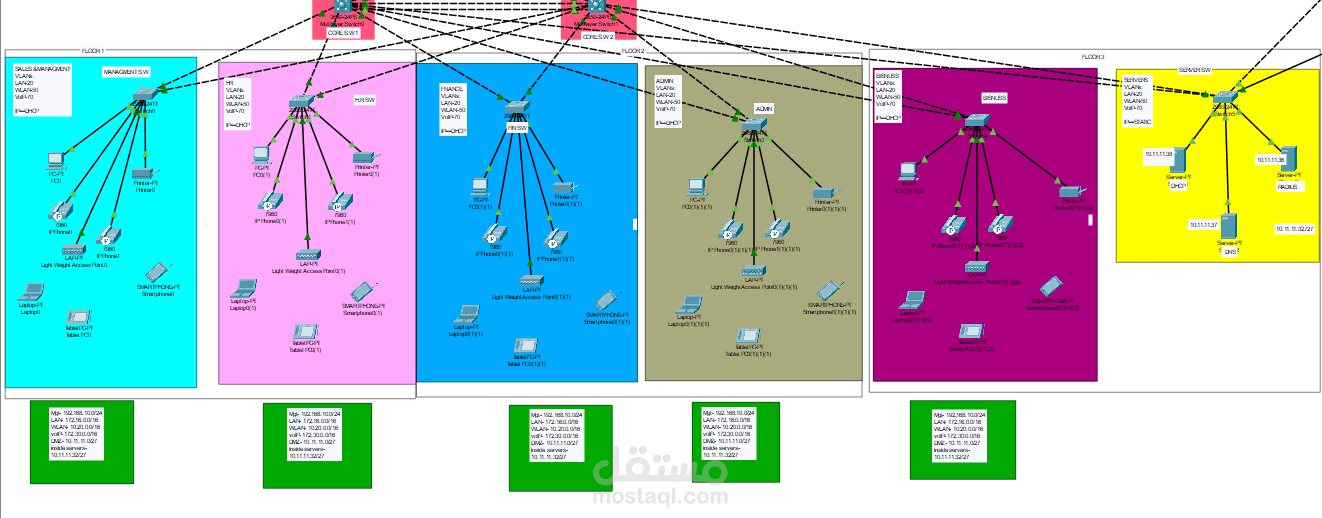
This project is an enterprise network design built in Cisco Packet Tracer. It includes dual ISP connectivity, two firewalls, a Core layer, floors segmented by VLANs, and a DMZ for public-facing servers.
Overall Structure (Top to Bottom)
1. Internet and ISPs
An Internet cloud (Cluster0) connects to external users (PCs at 8.0.0.10 and 8.0.0.20 on network 8.0.0.0/8).
Two service providers: Orange-ISP (Router1) and WE-ISP (Router2), each a 2911 router.
Links between the routers and the cloud use /30 subnets such as 20.20.20.0/30 and 30.30.30.0/30.
This is a redundant design: if one ISP fails, the other keeps working.
2. Security Layer (Firewalls)
Two Cisco ASA 5506-X firewalls: FW1 and FW2.
Each router connects to its own firewall and also cross-connects to the other one, which gives a high level of High Availability.
The ASA-to-Core links use 10.2.2.0/30, 10.2.2.4/30, 10.2.2.8/30, and 10.2.2.12/30.
3. DMZ
Network 10.11.11.0/27 with a 2960 switch connecting the externally accessible servers:
SAML, WEB, FTP, APP, STORAGE
It is isolated from the internal network and attached to the firewall.
4. Core Layer
Two Layer 3 switches (3560-24PS): CORE.SW1 and CORE.SW2.
They connect to each other and to every floor switch through multiple links (the dashed lines), most likely EtherChannel/trunks for redundancy and bandwidth.
5. Access Layer (3 Floors)
Floor Departments
Floor 1 Sales & Management
Floor 2 HR, Finance, Admin
Floor 3 Business, and the Server SW
Each department has roughly the same components: PC, Laptop, Tablet, Smartphone, IP Phones (7960), Printer, and a Lightweight Access Point (for WLAN).
6. VLANs
Each department has 3 VLANs:
VLAN 20 / LAN: wired devices (172.16.0.0/16)
VLAN 50 / WLAN: Wi-Fi (10.200.0.0/16)
VLAN 70 / VoIP: phones (172.30.0.0/16)
Addresses are assigned via DHCP, while the inside servers (10.11.11.32/27) use static addresses.
7. Inside Servers (Server SW)
DHCP server (10.11.11.38)
DNS server (10.11.11.37)
RADIUS server (10.11.11.36) for authentication (likely AAA / 802.1X for Wi-Fi)
Network: 10.11.11.32/27
8. Management Network
One screenshot shows a PC connected to the Management1/1 port on the ASA, which suggests a separate management network for the firewall.
Key Design Concepts
Hierarchical design: Core / Distribution / Access.
High Availability: dual ISP, dual firewall, dual Core.
Segmentation: per-department VLANs plus a separate DMZ.
Security: ASA firewalls and RADIUS.
Voice, wireless, and data all running on the same infrastructure.
If you'd like, I can write a project report or documentation, explain the configurations likely needed for implementation (OSPF, NAT, ACLs, HSRP, EtherChannel), or prepare a presentation about it.