Firewalls in EVE_NG
تفاصيل العمل
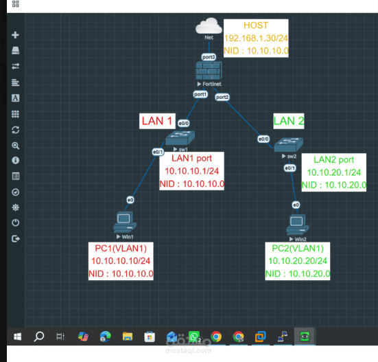
Network Topology Architecture & Overview
This topology illustrates a secured enterprise network deployment using a Fortinet (FortiGate) Firewall as the central security gateway and routing appliance, interconnecting two internal LAN segments with an external/host network.
1. FortiGate Firewall Interfaces
port1 (LAN 1 Gateway): IP: 10.10.10.1/24 | Subnet: 10.10.10.0/24
port2 (LAN 2 Gateway): IP: 10.10.20.1/24 | Subnet: 10.10.20.0/24
port3 (WAN / Host Interface): IP: 192.168.1.30/24 | Connected to Management/External Cloud Network
2. Network Segments & Endpoints
LAN 1 Subnet (10.10.10.0/24)
Switch (sw1): Connected to FortiGate port1 via interface e0/0.
PC1 (Win1): IP: 10.10.10.10/24 | VLAN 1 | Connected to sw1 port e0/1 with default gateway 10.10.10.1.
LAN 2 Subnet (10.10.20.0/24)
Switch (sw2): Connected to FortiGate port2 via interface e0/0.
PC2 (Win2): IP: 10.10.20.20/24 | VLAN 1 | Connected to sw2 port e0/1 with default gateway 10.10.20.1.
3. Key Technical Highlights
Centralized Firewall Routing: FortiGate acts as the default gateway for both subnets, enforcing security policies and controlling inter-zone traffic between LAN 1 and LAN 2.
External Uplink (WAN): port3 routes internal traffic to the external environment, supporting NAT configurations and internet access control.