Routing in EVE_NG
تفاصيل العمل
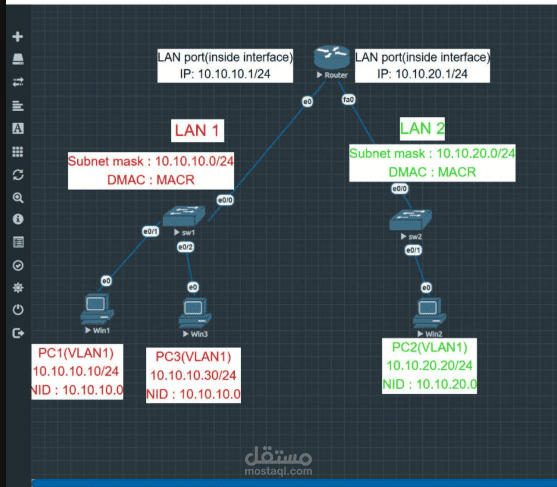
Network Topology Architecture & Overview
This topology consists of two local area networks (LAN 1 and LAN 2) interconnected via a central Router to enable inter-subnet routing.
1. LAN 1 Subnet
Network Address: 10.10.10.0/24
Gateway IP (Router Interface e0): 10.10.10.1/24
Switch: sw1 connected to the router via interface e0/0.
Connected Hosts:
PC1 (Win1): IP: 10.10.10.10/24 | VLAN 1 | Connected via port e0/1
PC3 (Win3): IP: 10.10.10.30/24 | VLAN 1 | Connected via port e0/2
2. LAN 2 Subnet
Network Address: 10.10.20.0/24
Gateway IP (Router Interface fa0): 10.10.20.1/24
Switch: sw2 connected to the router via interface e0/0.
Connected Hosts:
PC2 (Win2): IP: 10.10.20.20/24 | VLAN 1 | Connected via port e0/1
3. Key Technical Highlights
Subnet Segmentation: Logical separation between LAN 1 (10.10.10.0/24) and LAN 2 (10.10.20.0/24).
Default Gateways: Router interfaces serve as default gateways for their respective endpoints, allowing traffic to route across subnets.