Smart Security Alarm System
تفاصيل العمل
This project represents a digital smart alarm system designed using logic gates. The system controls alarm activation based on sensor inputs, access permission, and password verification.
Key Features:
1. Alarm Activation Logic (AL)
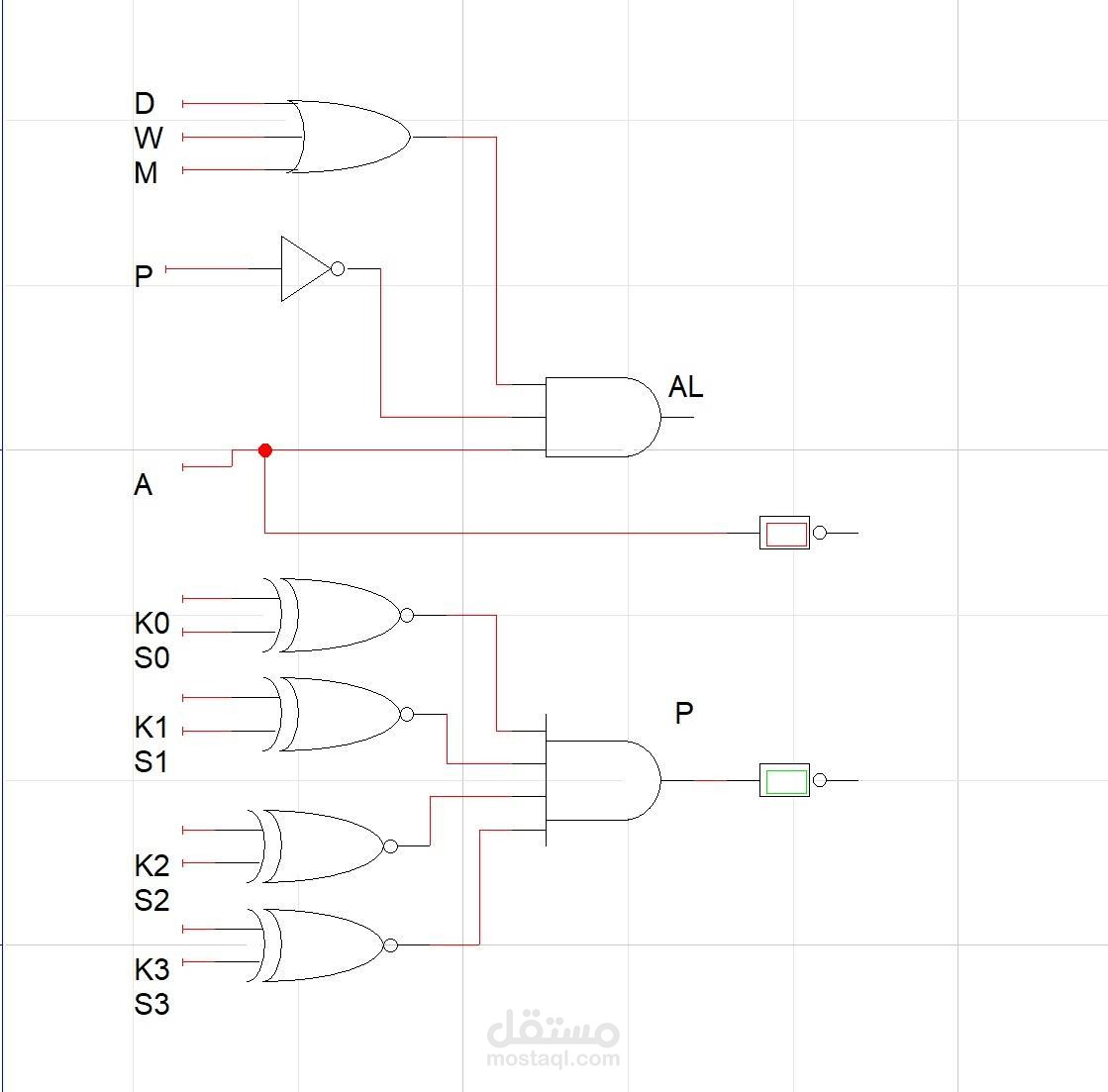
The alarm output (AL) is controlled using multiple conditions:
Inputs D, W, M are connected to an OR gate:
D = Door Sensor
W = Window Sensor
M = Motion Sensor
If any of these sensors detect activity, the OR gate becomes active.
Input P passes through a NOT gate, meaning:
If permission/password is not valid, the signal becomes active.
Input A acts as the main system enable/arm switch.
These signals are connected to an AND gate.
Alarm Logic Equation:
AL = (D + W + M) · P̅ · A
This means the alarm will activate only when:
At least one sensor is triggered
Permission is denied / password incorrect
System is armed
2. Password Verification Logic (P)
The lower section checks the correctness of a 4-bit password using four pairs of inputs:
K0 compared with S0
K1 compared with S1
K2 compared with S2
K3 compared with S3
Each pair uses logic comparison gates, and all outputs are connected to a final AND gate.
Password Output:
P = 1 only when all entered bits match the stored bits.
This means access is granted only if the full password is correct.
System Operation:
If the system is armed (A = 1)
A sensor detects intrusion
And the password is incorrect
➡️ Alarm turns ON
If the password is correct:
➡️ Alarm remains OFF
Project Objective:
To design a digital home/office security system using logic gates that combines intrusion sensors with password authentication for improved protection.