القاهرة
تفاصيل العمل
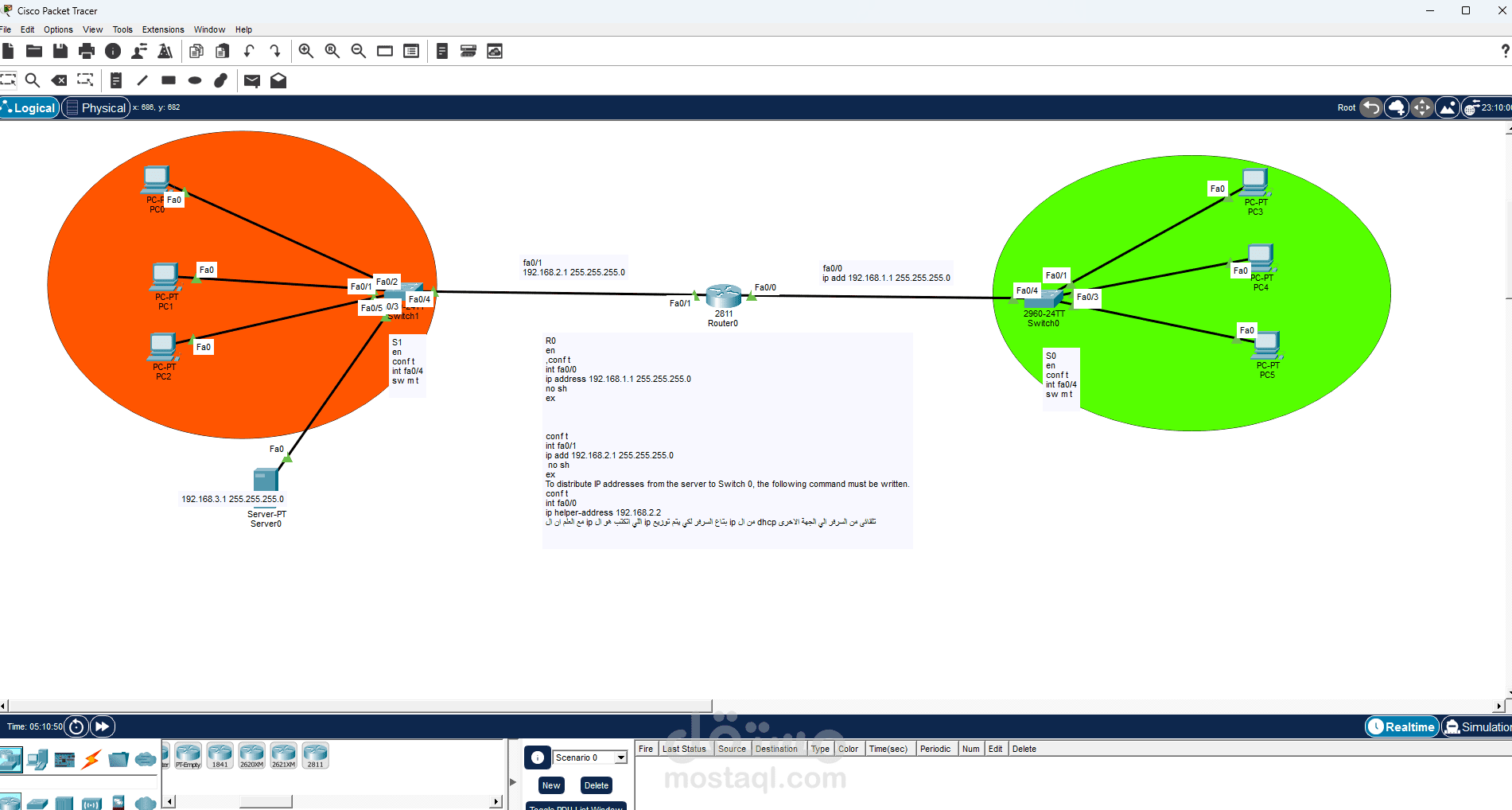

Left Side (Orange Area)
The orange section represents the first LAN. It contains:
Three PCs
One server
One switch
All of these devices are connected to the switch. The switch works as the central connection point for the devices in this network.
2. Right Side (Green Area)
The green section represents the second LAN. It contains:
Three PCs
One switch
Just like the first network, all devices in this LAN are connected to the switch.
3. Middle Section
In the center of the topology, there is a router connecting the two switches.
The router is responsible for allowing communication between the two different networks.
Function of Each Device
PCs
The PCs are end-user devices used to send and receive data within the network.
Switch
The switch connects devices within the same LAN and forwards data based on MAC addresses.
Router
The router connects different networks together. In this topology, it allows devices in the orange LAN to communicate with devices in the green LAN.
Server
The server, located in the left LAN, is used to provide network services such as file sharing, web services, DNS, or other resources depending on the configuration.
Main Idea of the Topology
The main purpose of this network is to demonstrate how:
multiple devices can be connected inside a LAN using a switch,
two different LANs can be connected using a router,
and devices from one network can communicate with devices in another network.
This is a basic example of inter-network communication.
Data Flow in the Network
If a PC in the orange network wants to send data to a PC in the green network, the process is usually:
The PC sends the data to the switch
The switch forwards it to the router
The router determines the correct destination network
The router sends the data to the other switch
The switch delivers it to the target PC
So:
Communication within the same LAN is handled by the switch
Communication between different LANs is handled by the router
Notes About the Diagram
The orange and green colors are used to visually separate the two networks.
The labels such as Fa0/1, Fa0/0, Fa0/24 indicate the FastEthernet ports used for the connections.
There is also a small text box in the middle that appears to contain IP addressing or router configuration notes, but the text is not fully clear in the image.
Conclusion
This diagram represents a simple but important network model in Packet Tracer. It shows how two LANs can be connected through a router, allowing communication between different groups of devices. It also demonstrates the roles of switches, PCs, and a server in a basic network environment.
If you want, I can also give you one of these in English:
A short academic paragraph
A simple easy-English explanation
A presentation-style explanation
A ready-to-submit report version
If you want, I can rewrite it in a more formal university style.