VLANs
تفاصيل العمل
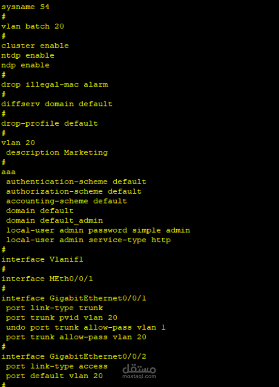
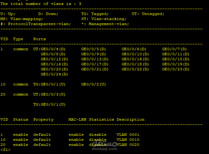
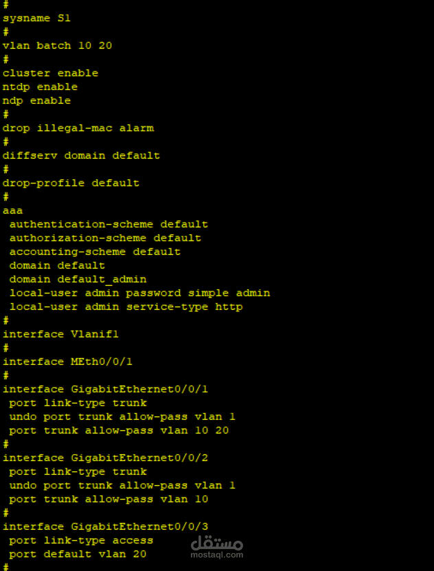
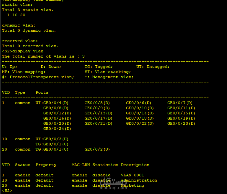
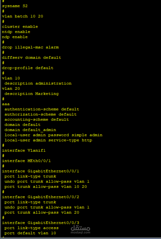
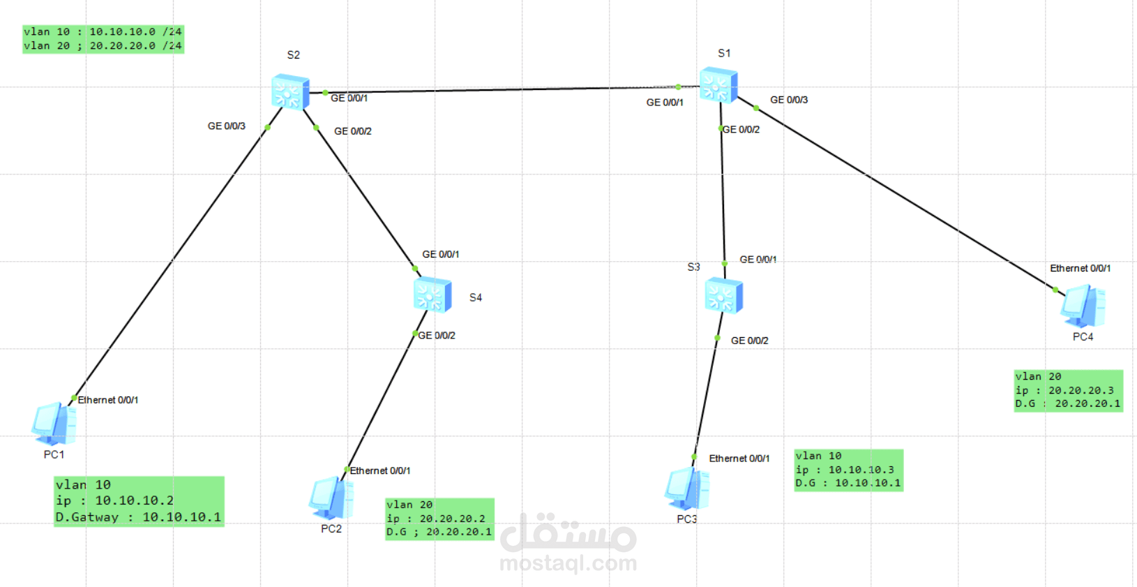
This network topology shows four switches (S1-S4) and four PCs, configured with two separate VLANs:
* VLAN 10: 10.10.10.0 /24 (Gateway: 10.10.10.1)
* VLAN 20: 20.20.20.0 /24 (Gateway: 20.20.20.1)
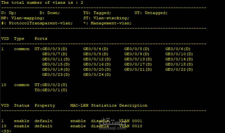
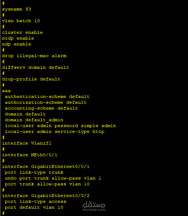
PC1 (10.10.10.2) connects to S2, and PC3 (10.10.10.3) connects to S3; both are in VLAN 10.
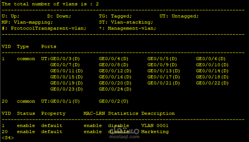
PC2 (20.20.20.2) connects to S4, and PC4 (20.20.20.3) connects to S1; both are in VLAN 20.
The switches are interconnected, with S1 linking to S2 and S3, and S2 also linking to S4, forming the core switch infrastructure.
تُظهر بنية الشبكة هذه أربعة مبدلات (S1-S4) وأربعة أجهزة كمبيوتر (PC)، مُهيأة ضمن شبكتين محليتين افتراضيتين (VLANs) منفصلتين:
* **VLAN 10:** بالشبكة 10.10.10.0 /24 (البوابة الافتراضية: 10.10.10.1)
* **VLAN 20:** بالشبكة 20.20.20.0 /24 (البوابة الافتراضية: 20.20.20.1)
الجهاز PC1 (10.10.10.2) متصل بالمبدل S2، والجهاز PC3 (10.10.10.3) متصل بالمبدل S3؛ وكلاهما في VLAN 10.
الجهاز PC2 (20.20.20.2) متصل بالمبدل S4، والجهاز PC4 (20.20.20.3) متصل بالمبدل S1؛ وكلاهما في VLAN 20.
المبدلات متصلة ببعضها البعض، حيث يتصل S1 بكل من S2 و S3، ويتصل S2 أيضًا بـ S4، مما يشكل البنية التحتية الأساسية للمبدلات.