University Network Design Project
تفاصيل العمل
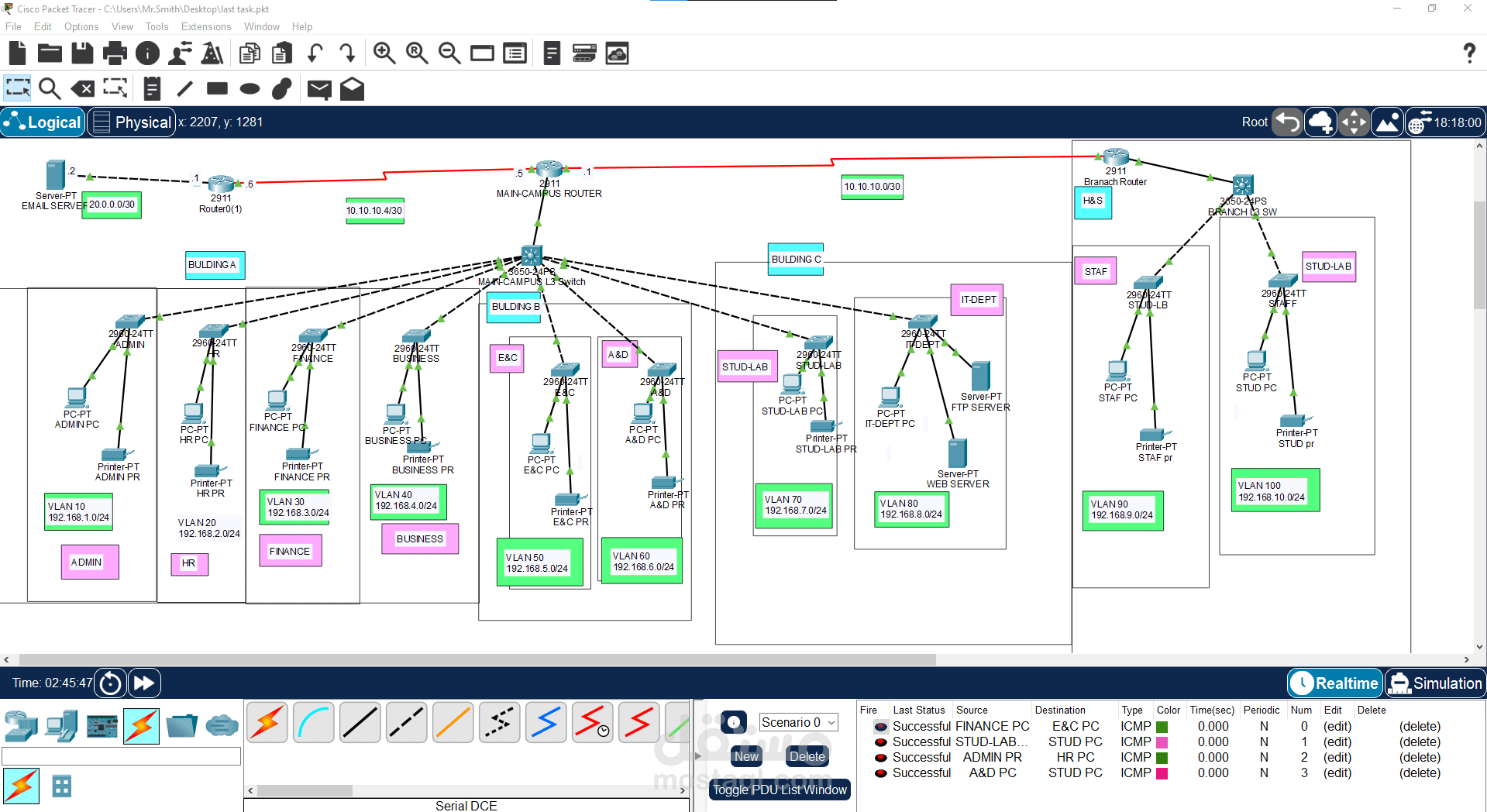
Main Building (3 Sub-Buildings), Each connected to a Layer 3 switch
Building A:
Contains 4 departments. Each department has:
Assigned to its own VLAN from VLAN 10 to VLAN 40
Building B:
Has 2 departments, each has:
Assigned VLAN 50 and VLAN 60
Building C:
Has 2 sections:
One section hosts a Web Server and an FTP Server in VLAN 80
The second section uses VLAN 70
Second Building
Contains 2 departments:
Each connected to a Layer 3 switch
Assigned VLAN 90 and VLAN 100
? Key Technologies Used:
VLAN Configuration
Each department/section is segmented using VLANs (from VLAN 10 to 100) for better security, traffic management, and broadcast isolation.
VLANs were defined on the Layer 3 Switch with proper interface configurations.
Trunk & Access Ports
*Access ports were used to connect end devices (PCs and printers) to their designated VLANs.
*Trunk ports were configured to carry multiple VLANs between switches and to the Layer 3 switch.
Layer 3 Switch
Used for Inter-VLAN Routing within each building to enable communication between VLANs while maintaining segmentation.
DHCP Configuration
· Configured DHCP pools on both the Main Campus router and the Second Campus router to automatically assign IP addresses to hosts in their respective VLANs.
· Each router handles DHCP for its local VLANs, ensuring devices in each building receive the correct IP
management.
Main Router (Main Campus Router)
Connects:
The Main Building’s Layer 3 Switch
The Second Building’s Layer 3 Switch
A separate Mail Server
Routing Protocol: Configured RIP Version 2 for dynamic routing between buildings and the mail server router.
Serial Connection
Used serial connections between routers (DCE/DTE) to simulate WAN-like links and enable inter-building routing.