SolidWorks Freelancer
تفاصيل العمل

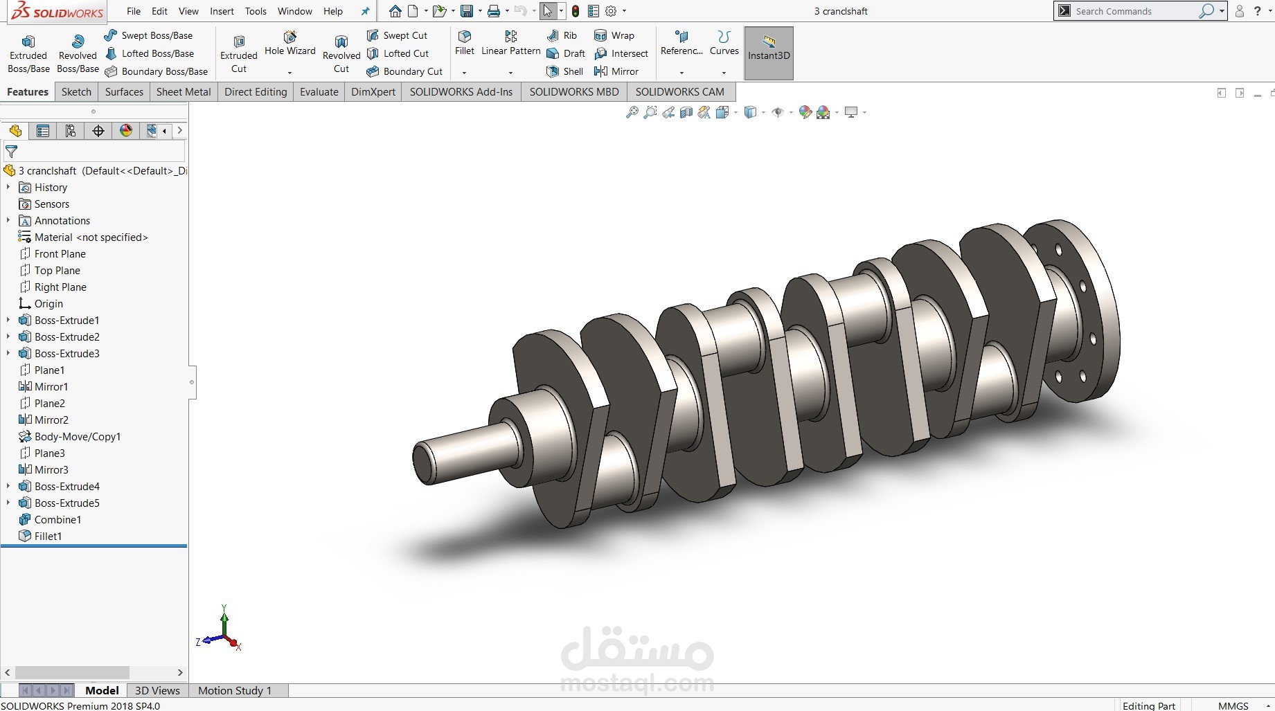
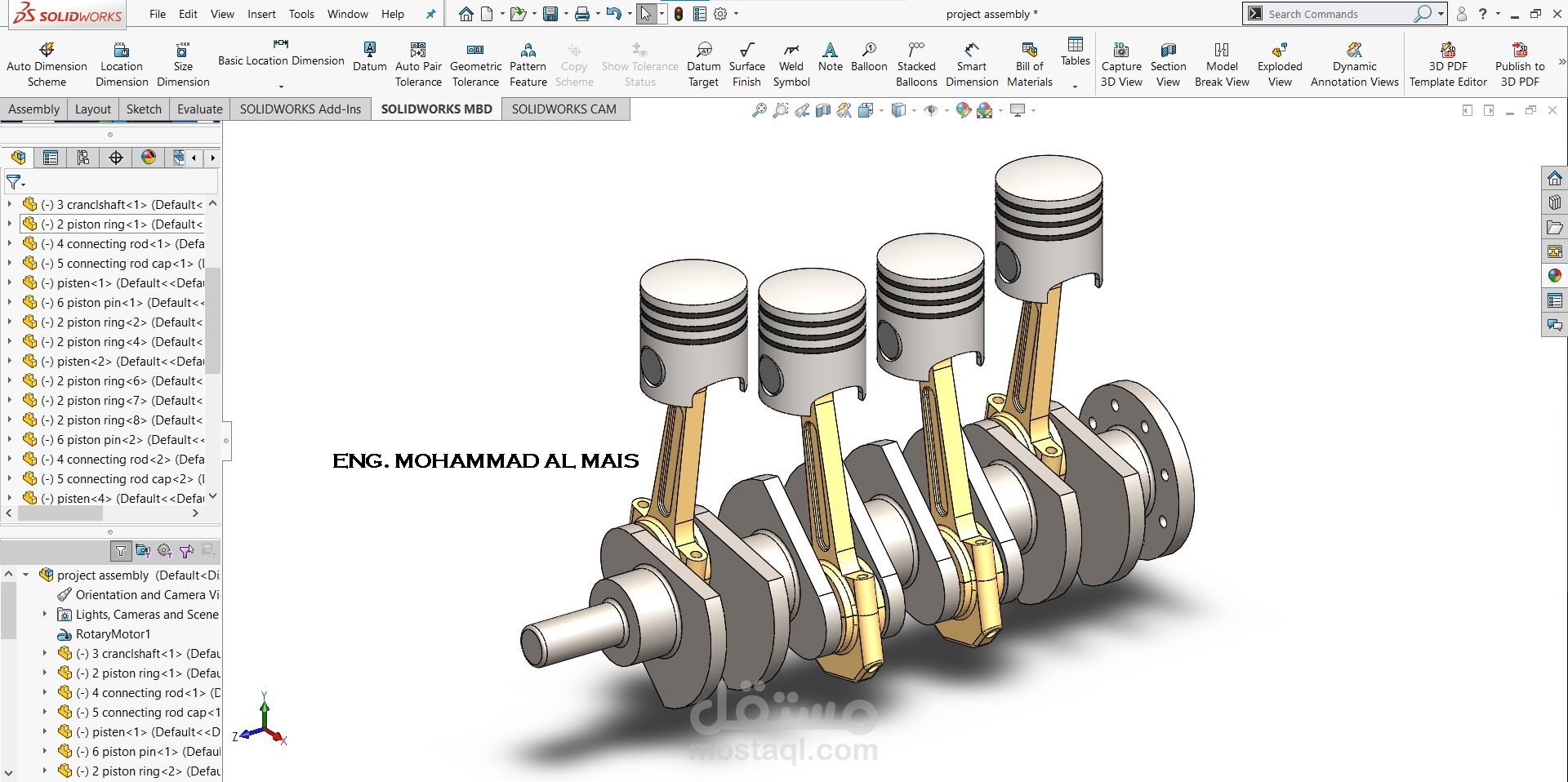
This SolidWorks model represents a four-cylinder inline engine crankshaft–piston assembly.
Technical Description:
Crankshaft: A multi-throw crankshaft designed with four crankpins offset at equal intervals to convert the reciprocating motion of pistons into rotary motion. Counterweights are included to balance dynamic forces and reduce vibration.
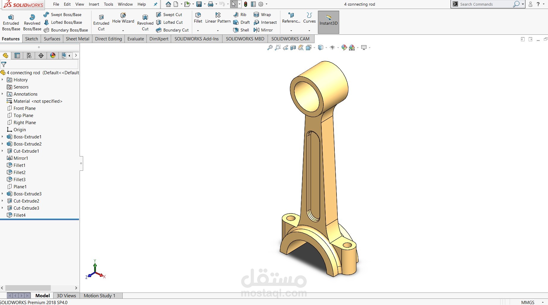
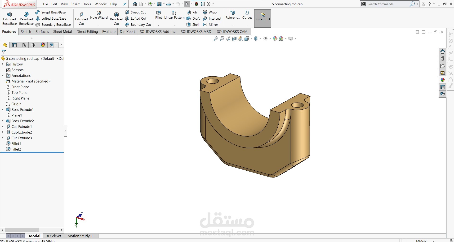
Connecting Rods: Four connecting rods link the pistons to the crankshaft, transmitting the reciprocating piston force into torque. The rod caps and bolts are modeled for proper fastening.
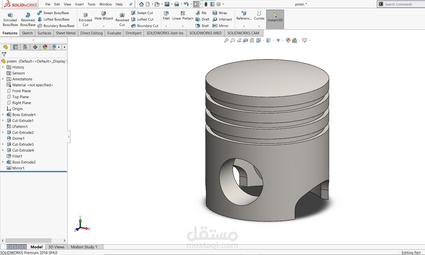
Pistons: Four pistons with grooves for piston rings, ensuring compression sealing and minimizing blow-by.
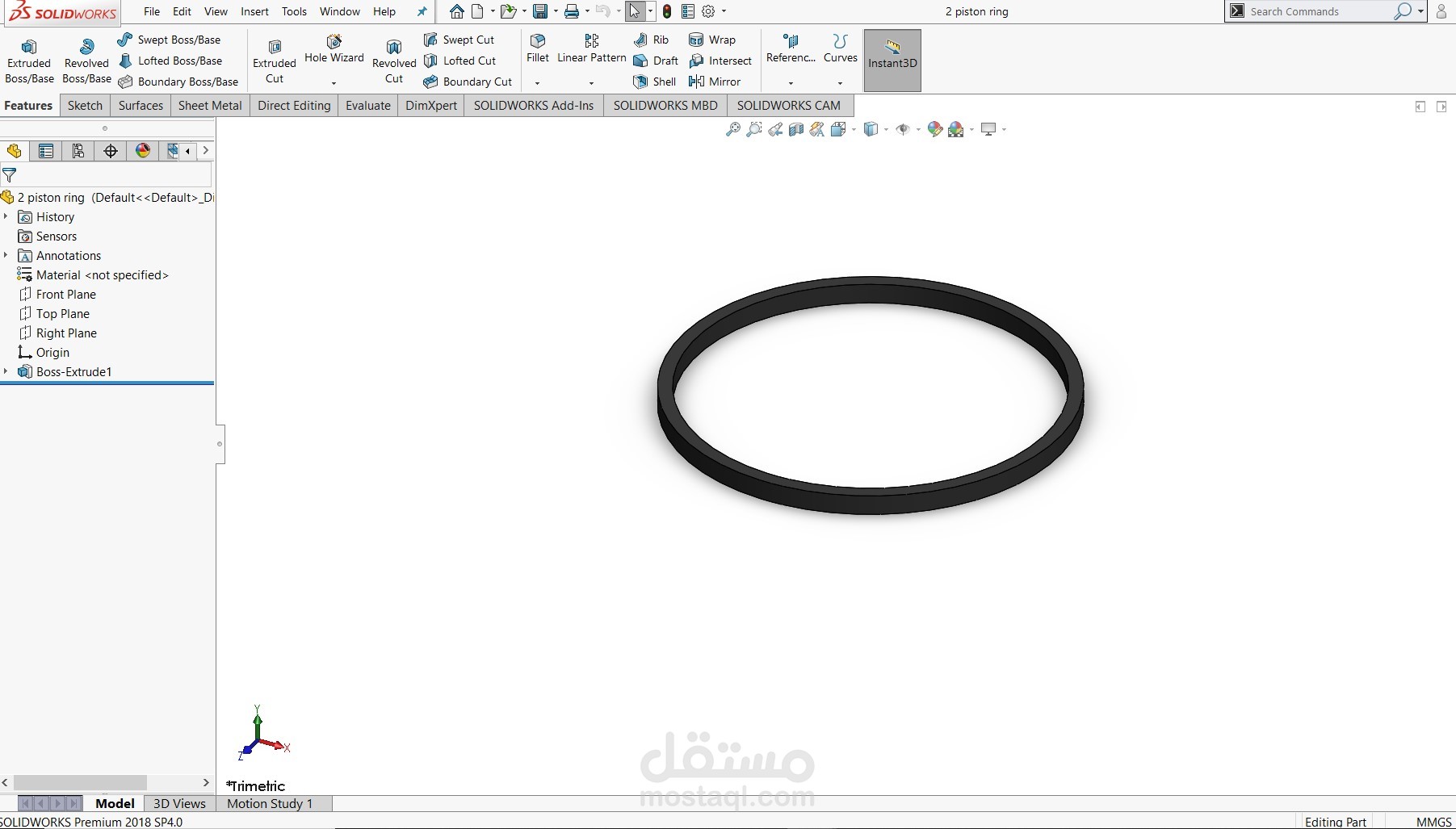
Piston Rings: Modeled to represent compression and oil control rings, providing sealing, lubrication control, and heat transfer from piston to cylinder wall.
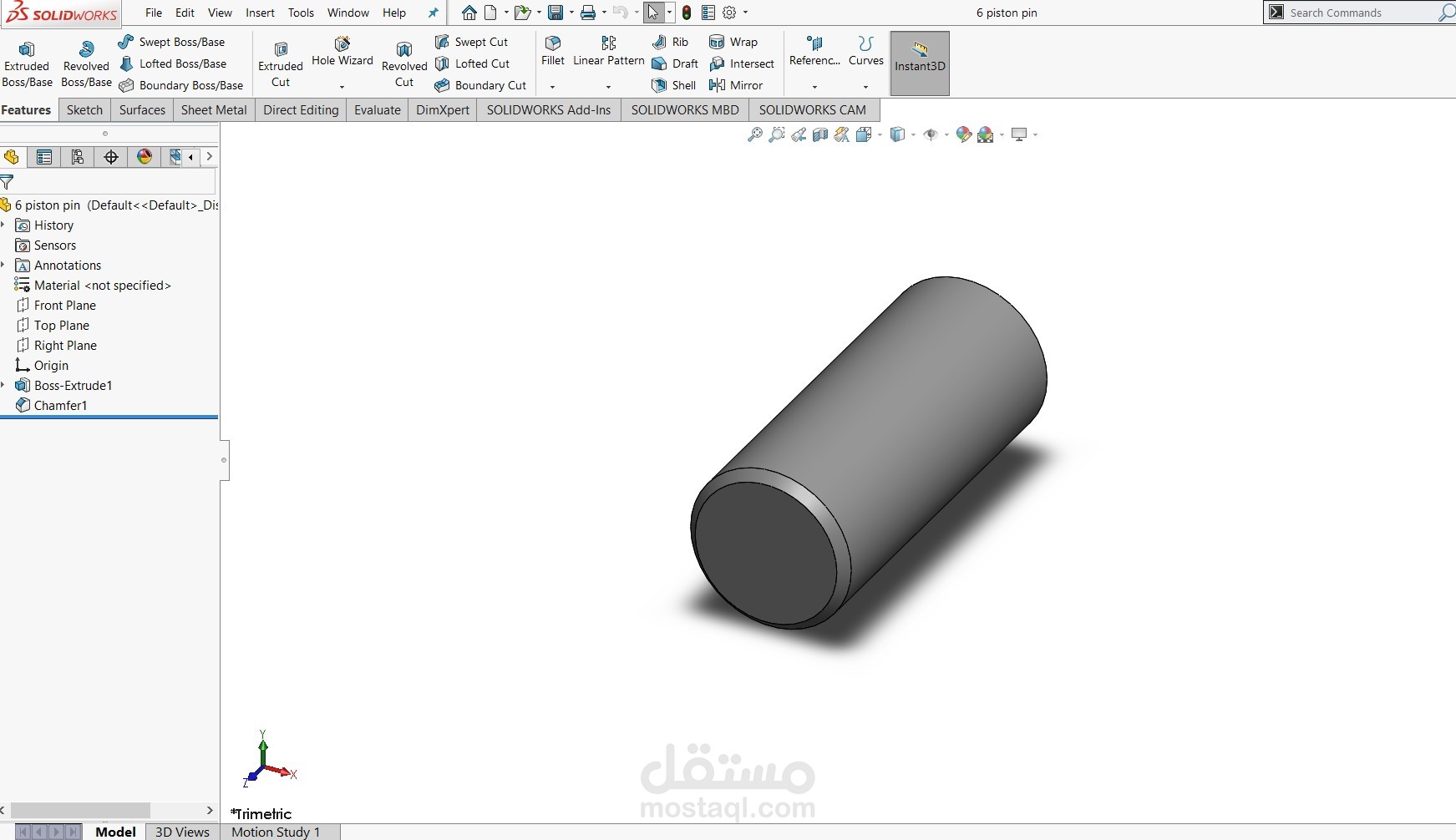
Piston Pins (Gudgeon Pins): Each piston is connected to its respective connecting rod through a pin joint, allowing free rotation and smooth motion transmission.
Flywheel Mounting: The crankshaft end includes a flange for mounting a flywheel or power transmission element, stabilizing rotational motion and delivering torque output.
Functionality:
This assembly demonstrates the working principle of an internal combustion engine where the linear reciprocating motion of pistons is converted into continuous rotary motion of the crankshaft. Such configurations are widely used in automotive and industrial engines, offering smooth operation due to the balanced inline-four design.