Full Wave Rectifier Simulation
تفاصيل العمل
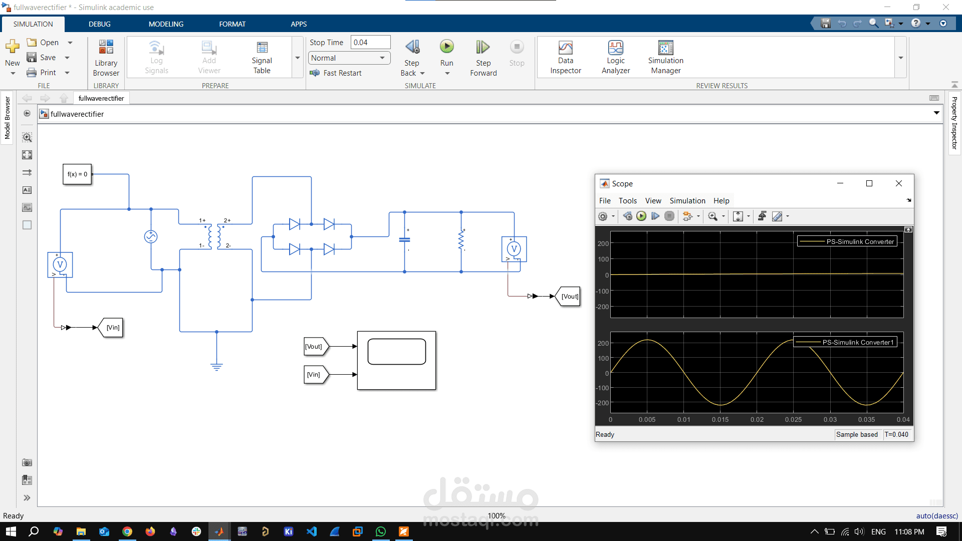
This simulation demonstrates the operation of a full-wave rectifier using Simulink. The model converts an AC input voltage into a pulsating DC output using a bridge rectifier configuration, which consists of four diodes arranged in a bridge circuit. A resistive load is connected to observe the output waveform.
The AC source provides a sinusoidal input, and the diodes conduct alternately during each half-cycle of the input signal, ensuring that current flows in the same direction through the load during both halves. This results in a full-wave rectified output. The output waveform and input signal are monitored using Scope blocks to visualize the rectification process.
Optional components, such as a filter capacitor, can be added to smooth the output for a more constant DC voltage, showcasing the difference between unfiltered and filtered rectification.
Key Components:
AC Voltage Source
Bridge Diode Network (Full Wave Rectifier)
Resistive Load (R)
Capacitor (optional, for filtering)
Scope (to view waveforms)