UVC disinfection PCB
تفاصيل العمل
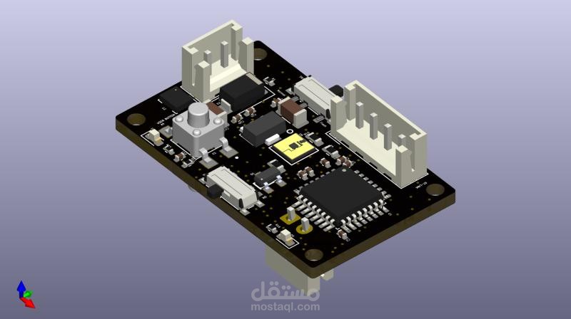
A very, very compact PCB, at just 21mm x 35mm, designed as a double-layer PCB, and integrates a smart power control system alongside motion-based UVC LED activation, and is able to last +30 days on battery.
The board features:
1- MCU: STM32L031K6T – a low-power Cortex-M0+ MCU to handle control logic efficiently.
2- Motion Sensing: LSM6DS3 – a 3D accelerometer & gyroscope determines orientation to activate the correct UVC LED.
3- UVC LEDs: 2x 254nm LEDs (23mW, 150mA) – ensure effective disinfection, switching every 60 minutes for 90 seconds based on orientation.
4- Power Management:
- L7BM06CDT (6V regulator)
- L78L33ACUTR (3.3V regulator) for the MCU
- MCP73831-2-MC (Li-ion charging IC) for battery management
5- User Interface & Control:
- Status LEDs (2x) & Power LED (1x) for feedback.
- A user button for additional interaction.
- Power Button using D Flip-Flop (74HC74) – holds power after a 5-second press, controlled via an RC delay circuit.
Instead of an always-on MCU (to save the battery), the device remains completely powered off until the user presses the power button for 5 seconds.
Uses a D flip-flop latch circuit with an RC network to ensure accidental presses don’t turn it on.
- ON/OFF Switch for direct power control when needed.
- 4-pin JST connector for ST-LINK interface
- Two 2-pin JST connector for the batteries and their charger
A very, very compact PCB, at just 21mm x 35mm, designed as a double-layer PCB, and integrates a smart power control system alongside motion-based UVC LED activation, and is able to last +30 days on battery. The board features: 1- MCU: STM32L031K6T – a low-power Cortex-M0+ MCU to handle control logic efficiently. 2- Motion Sensing: LSM6DS3 – a 3D accelerometer & gyroscope determines orientation to activate the correct UVC LED. 3- UVC LEDs: 2x 254nm LEDs (23mW, 150mA) – ensure effective disinfection, switching every 60 minutes for 90 seconds based on orientation. 4- Power Management: - L7BM06CDT (6V regulator) - L78L33ACUTR (3.3V regulator) for the MCU - MCP73831-2-MC (Li-ion charging IC) for battery management 5- User Interface & Control: - Status LEDs (2x) & Power LED (1x) for feedback. - A user button for additional interaction. - Power Button using D Flip-Flop (74HC74) – holds power after a 5-second press, controlled via an RC delay circuit. Instead of an always-on MCU (to save the battery), the device remains completely powered off until the user presses the power button for 5 seconds. Uses a D flip-flop latch circuit with an RC network to ensure accidental presses don’t turn it on. - ON/OFF Switch for direct power control when needed. - 4-pin JST connector for ST-LINK interface - Two 2-pin JST connector for the batteries and their charger
Skills: KiCAD · Printed Circuit Board (PCB) Design · Electronics Hardware Design · STM32