Network-simulation
تفاصيل العمل
Introduction
Network Topologies
Bus Topology
Ring Topology
Tree Topology
Star Topology
Implementation Details
Bus Topology
Ring Topology
Tree Topology
Star Topology
OSPF (Open Shortest Path First)
Virtual LANs (VLANs)
PAT (Port Address Translation)
Telnet
NAT (Network Address Translation)
FTP (File Transfer Protocol)
DNS (Domain Name System)
Configuration and Testing
Conclusion
1. Introduction
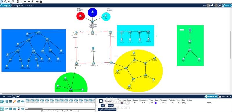
This report demonstrates the implementation of four different Local Area Network (LAN) topologies using Cisco Packet Tracer. The topologies include Bus, Ring, Tree, and Star. Each topology is connected to a router and comprises a specific number of switches. The report also includes IP addressing and subnetting for each building, utilizing Class C IPs only in networks 193.168.1.0 and 193.168.2.0.
2. Network Topologies
Bus Topology (Building B)
Routers: 1 router
Switches: 4 switches
Devices: PCs connected to each switch, totaling 36 hosts
Reason: Simple to implement and cost-effective for a small number of hosts. Requires less cabling and is easier to set up.
IP Subnetting:
Subnet Mask: 255.255.255.192
Network IP: 193.168.2.0
Broadcast IP: 193.168.1.63
First Valid IP: 193.168.2.2
Last Valid IP: 193.168.2.62
Default Gateway: 193.168.2.1
Wildcard Mask: 0.0.0.63
Star Topology (Building C)
Routers: 1 router
Switches: 1 switch
Devices: PCs connected to one switch, totaling 47 hosts
Reason: Ensures equal access to the network for all hosts and can handle moderate traffic well. Simplifies troubleshooting and network management.
IP Subnetting:
Subnet Mask: 255.255.255.192
Network IP: 193.168.2.64
Broadcast IP: 193.168.1.127
First Valid IP: 193.168.2.66
Last Valid IP: 193.168.2.126
Default Gateway: 193.168.2.65
Wildcard Mask: 0.0.0.63
Tree Topology (Building A)
Routers: 1 router
Switches: 11 switches
Devices: PCs connected to each switch, totaling 212 hosts
Reason: Ideal for hierarchical structure, efficient management, and scalability. Allows for organized traffic flow and reduced congestion.
IP Subnetting:
Subnet Mask: 255.255.255.0
Network IP: 193.168.1.0
Broadcast IP: 193.168.1.255
First Valid IP: 193.168.1.2
Last Valid IP: 193.168.1.254
Default Gateway: 193.168.1.1
Wildcard Mask: 0.0.0.255
Ring Topology (Building D)
Routers: 1 router
Switches: 5 switches
Devices: PCs connected to each switch, totaling 125 hosts
Reason: Provides equal access to the network for all hosts. Maintains network performance and reliability through circular data paths and rerouting in case of failure.
IP Subnetting:
Subnet Mask: 255.255.255.128
Network IP: 193.168.2.128
Broadcast IP: 193.168.1.255
First Valid IP: 193.168.2.130
Last Valid IP: 193.168.2.254
Default Gateway: 193.168.2.129
Wildcard Mask: 0.0.0.127
3. Implementation Details
This section covers the practical steps taken to implement each topology using Cisco Packet Tracer, including specific configuration details and the setup process for each topology.
4. OSPF (Open Shortest Path First)
Details the OSPF configurations and routing table setups used to ensure proper network routing across the implemented topologies.
5. Virtual LANs (VLANs)
Explains the creation and configuration of VLANs within the network, including isolated networks and VLAN IDs:
VLAN 10: 192.168.10.0/24
VLAN 20: 192.168.20.0/24
VLAN 30: 192.168.30.0/24
6. PAT (Port Address Translation)
Describes the configuration of PAT on the server router, utilizing a global IP address for external access.
7. Telnet
Covers the configuration of Telnet for remote access to routers, including setting up passwords.
8. NAT (Network Address Translation)
Details the NAT configuration between the bus and ring routers, noting an error due to interface overlap with OSPF.
9. FTP (File Transfer Protocol)
Implementation of an FTP server within an isolated network, including handling errors and the need for static NAT in the main network.
10. DNS (Domain Name System)
Configuration of a DNS server with an IP address of 10.10.10.2, mapping to a sample website.
11. Configuration and Testing
Step-by-step guide on:
Assigning IP addresses and subnet masks
Configuring switches with VLANs
Connecting LANs to routers
Testing connectivity within LANs
Ensuring correct router and switch configurations