DIY-Loads-management-in-solar-off-grid-inverters-Voltronic-inverter
تفاصيل العمل
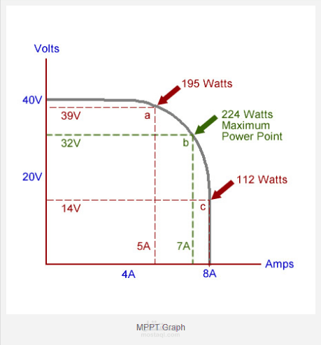

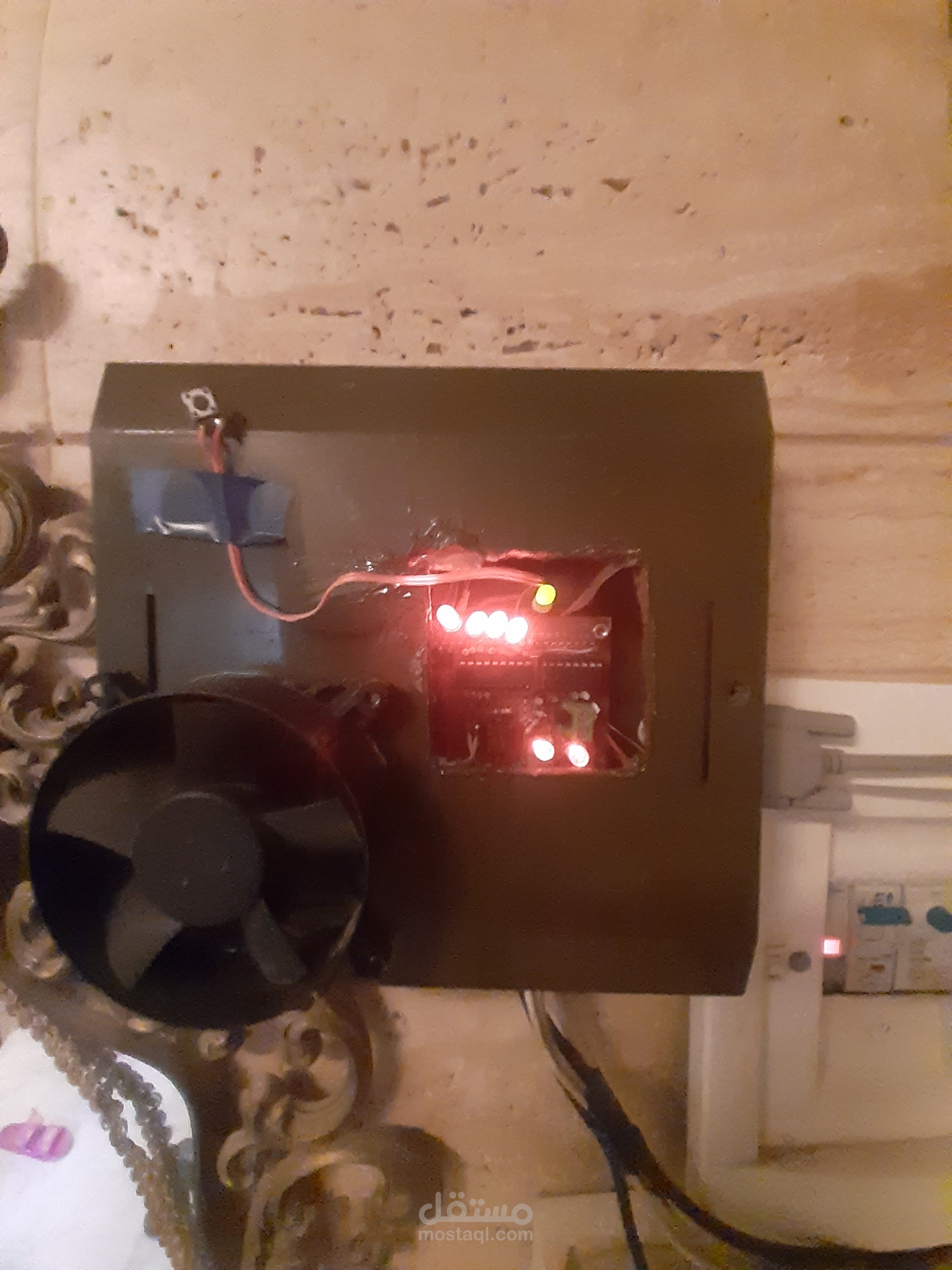
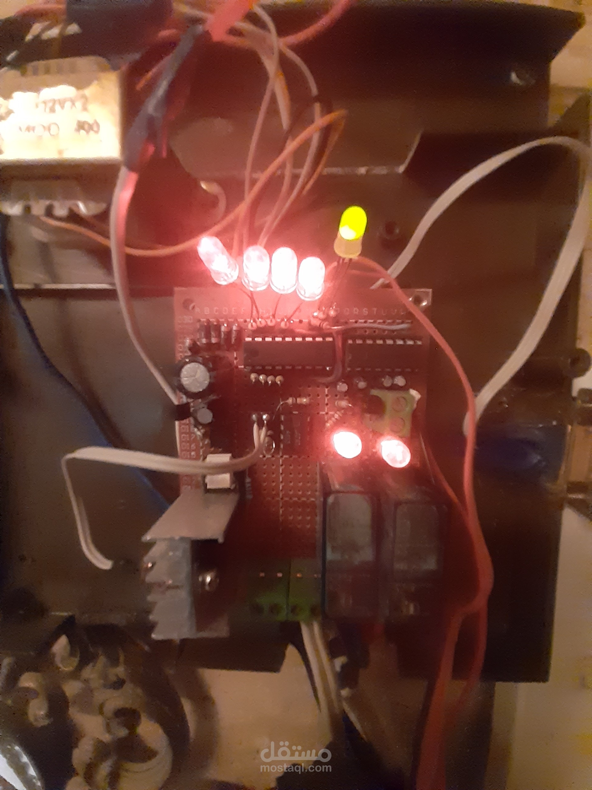
This project is aimed to organise the process of connecting the power loads to the inverter output. The inductive loads (refrigerator, freezer) will be connected and disconnected sequentially with certain delays in order to preserve both loads and inverter output from dynamic currents. Also the high power load (water heater) could be connected to the inverter output by limiting the load current. The control board is connected to the Voltronic inverter by a RS232 serial cable, to retrieve all necessarily data (battery voltage, battery charge and discharge current, PV voltage, PV current, grid power, and many other). The control board has one input power from the inverter (AC voltage 220v), and three power output, the first one for the refrigerator, the second for the freezer, and the last one for water heater. The refrigerator, and freezer are considered to be an inductive load, so connect both loads at the same time with all other loads could be harmful to the inverter and to the connected loads. When starting the inverter, the control board will delay connecting these inductive loads, until all other loads connected, after that the refrigerator will be first connected, and after while the freezer will be safely connected. The water heater cannot be connected directly to the inverter output, because the inverter cannot support the high power needed by the heater, and the inverter will switch off, and announce an overload error. The control board calculates the extra available power at the inverter output that not being used by the connected loads, and provide that power to the water heater. The control board manage the available power at the inverter output and switch that power in a safe way to the refrigerator, freezer, and water heater.